Wow, 2012 Got here way too
fast. We managed to get some painting done during the cold part of the
winter using electric heaters. The power bill has been about $80/mo to
keep the crew quarters dry and the areas where painting has taken place
warmed for a few days.
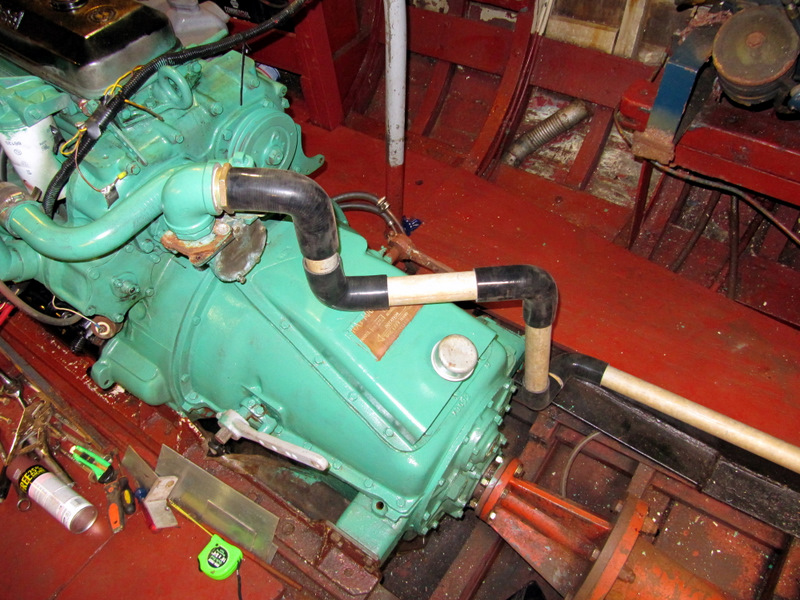
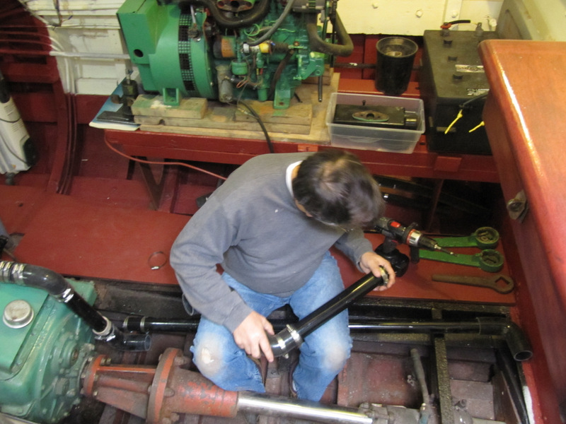
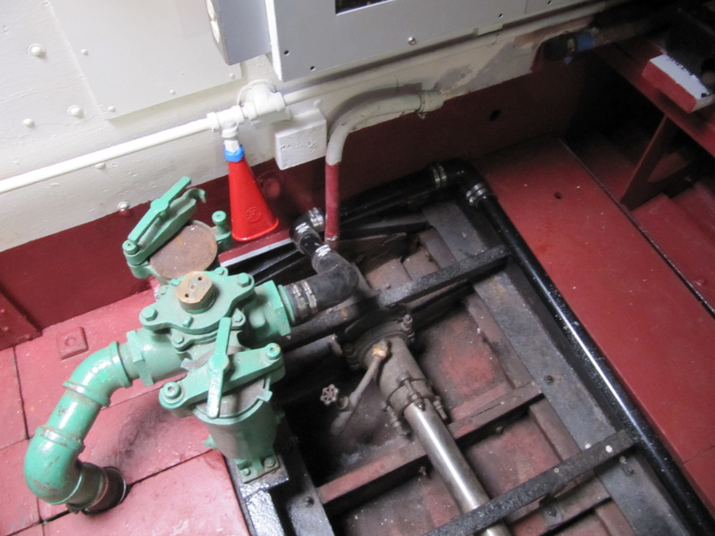
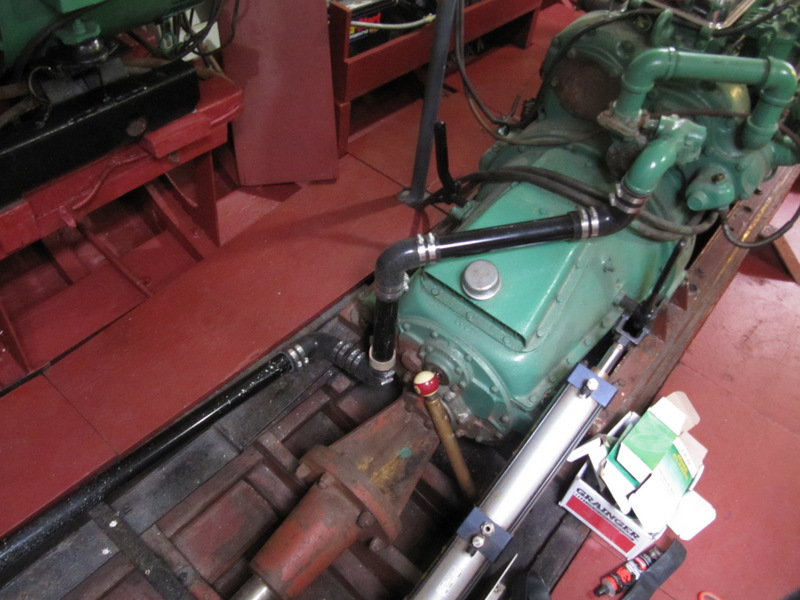
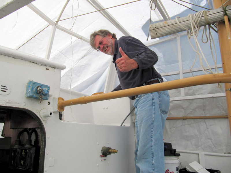
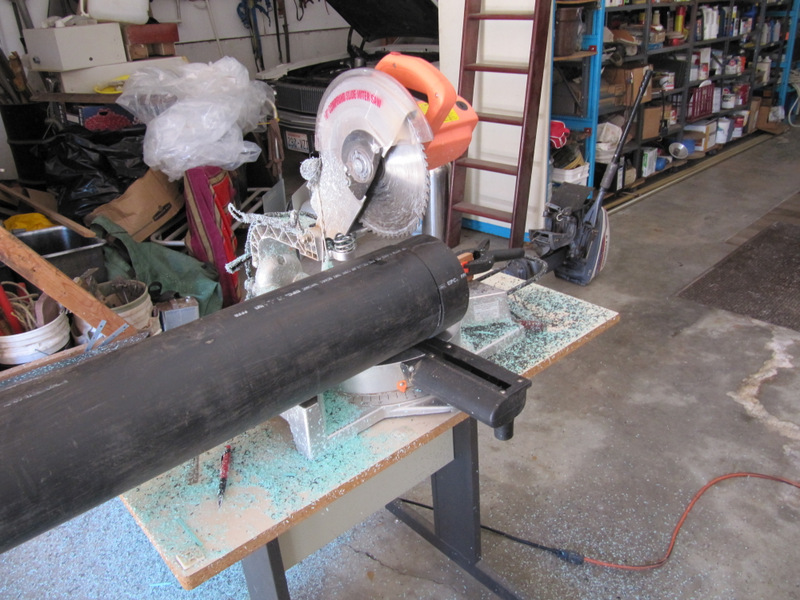
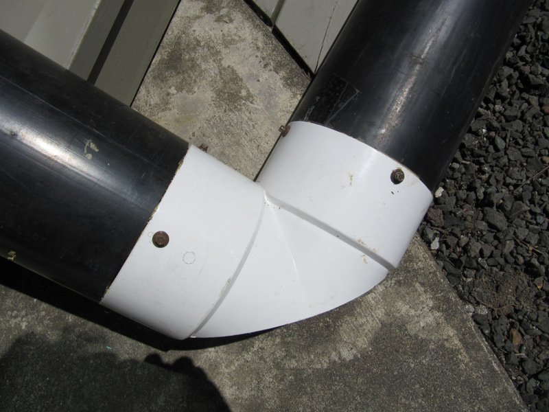
The crappy hose and clamp
setup supplying the raw water from the sea strainer to each engine pump
was removed and a new pipe and rubber elbow routing method was added. This is
volunteer and friend Larry Sanneman cutting and fitting.
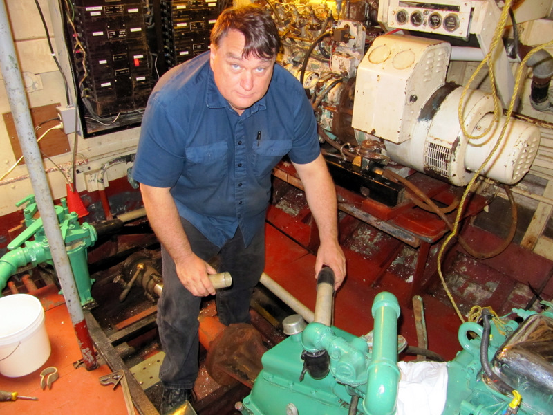
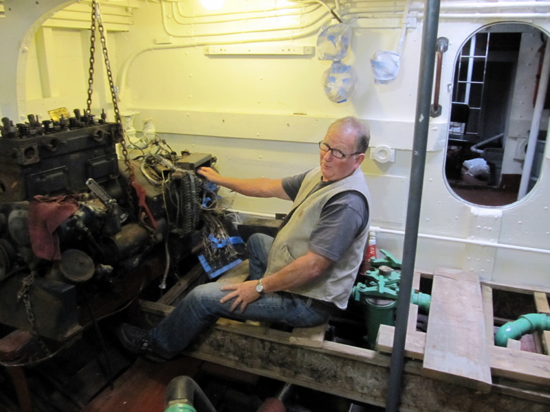
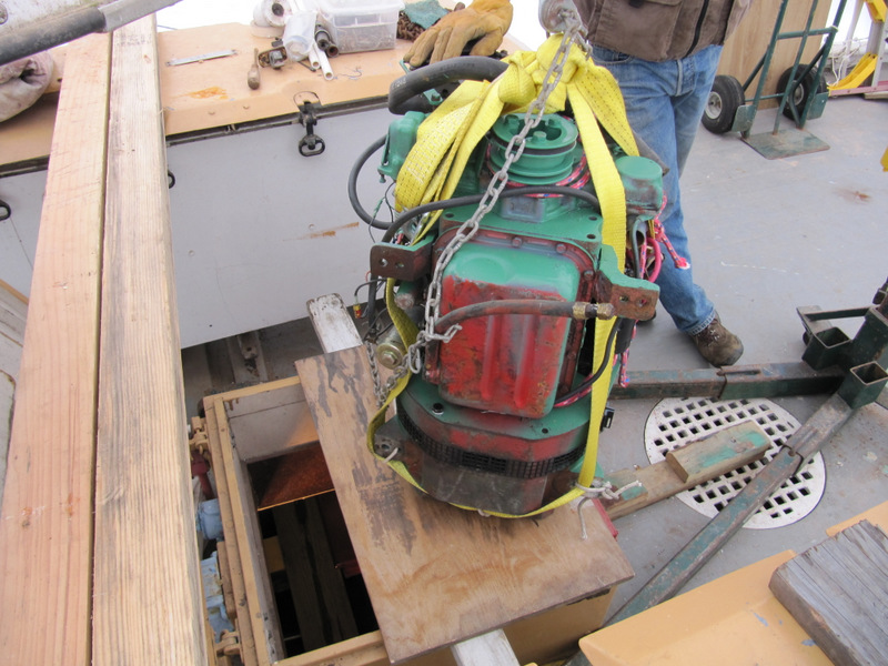
Due to the weight of the old engine and
generator we disassembled it down to the liftable size. Here is Mark
McCaffery assisting.
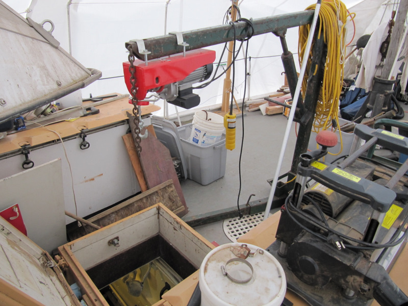
A heavy duty engine hoist was placed over
the aft engine room hatch. An electric winch was bolted to the end of
the lift arm. It was pretty easy to remove with this setup.
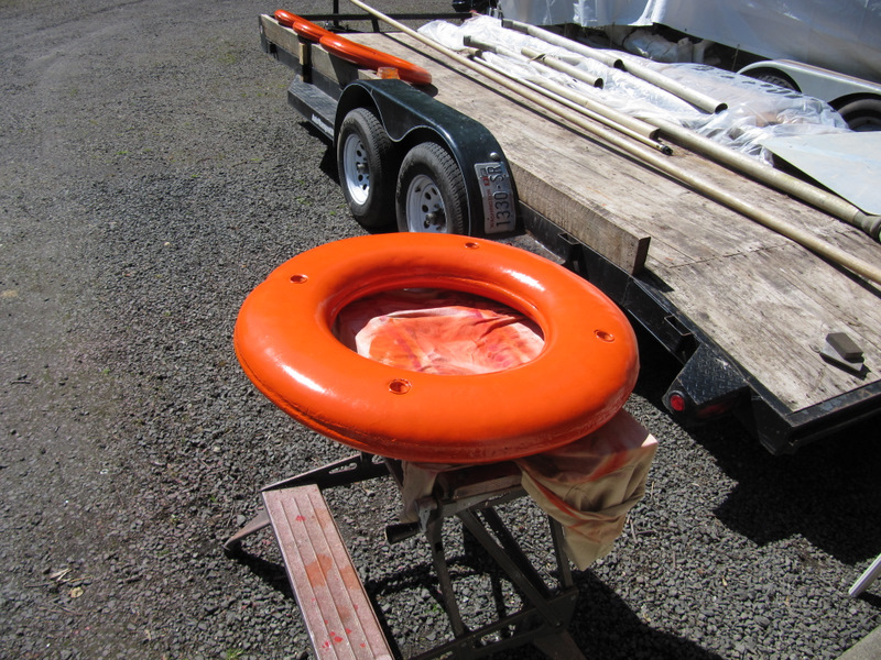
This from the late fall, I cleaned and
repainted each of the throw rings. I have the new boat name stickers to
add.
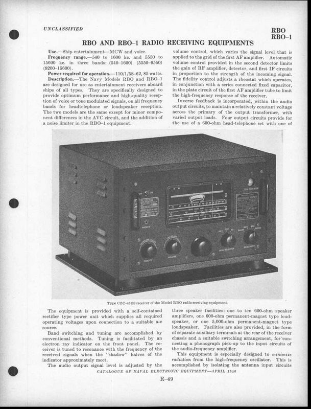
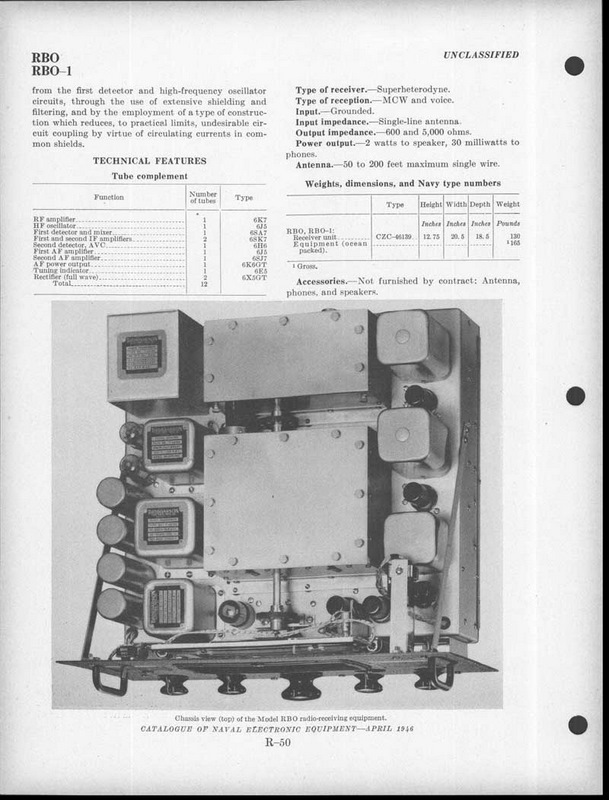
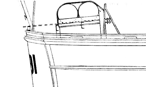
Photos of the 83527 and
other 83 footers show a RBO receiver in the crew quarters. They were
designated as ship entertainment receivers. We were donated one from the
Puget Sound Navy Museum in Bremerton. It does need some work however.
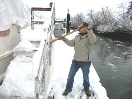
Volunteer John Cross is shoveling snow off
the gangway and helping get the smashed tarps back in shape.
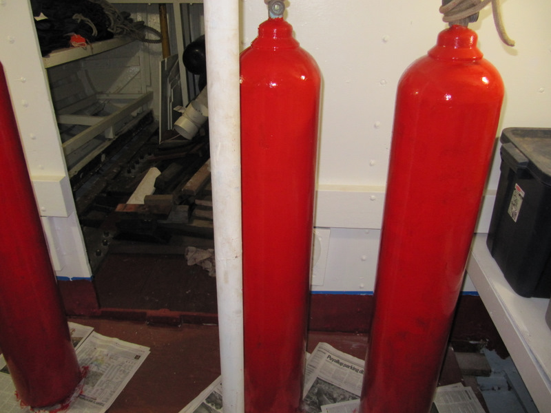
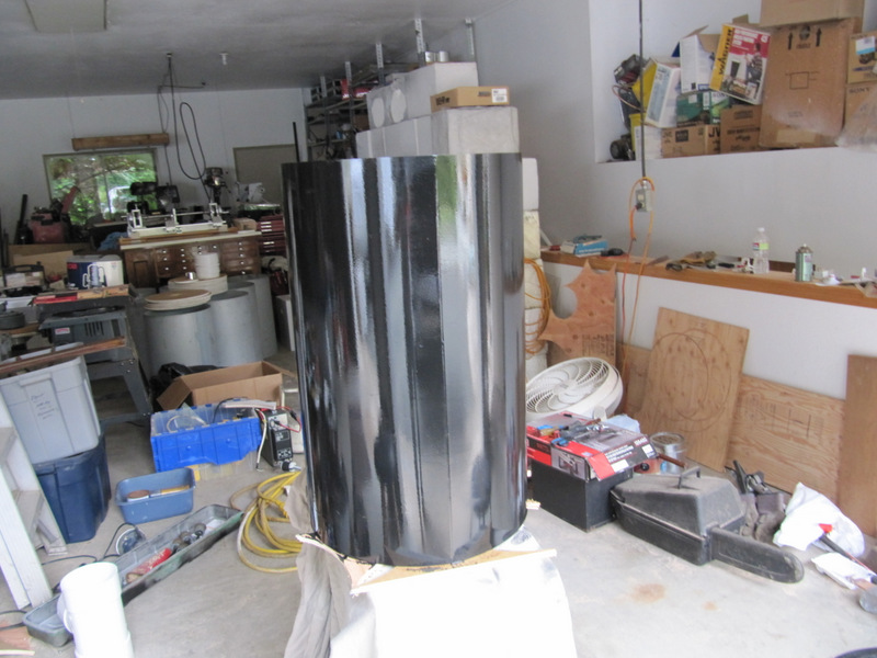
Painting the three CO2 bottles.
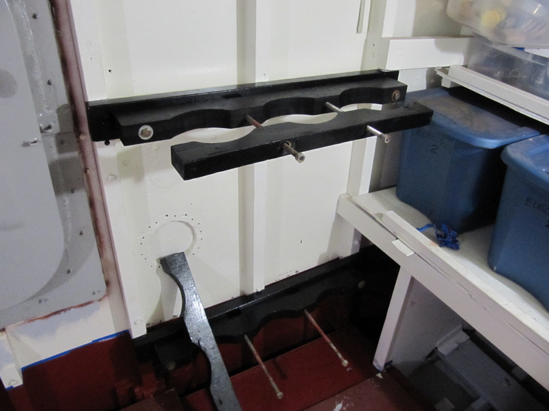
Painting the CO2 bottle mounts.
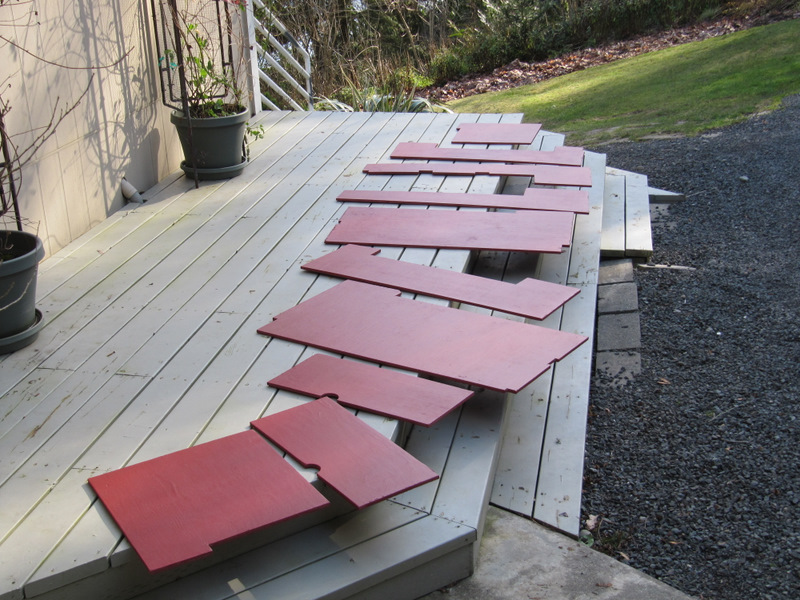
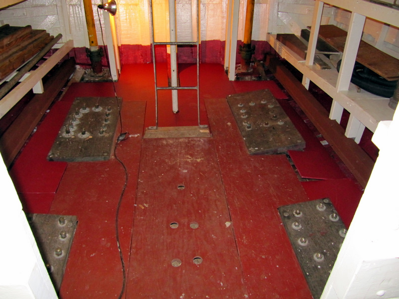
Painting the old and new floorboards from
engine room and lazerette.
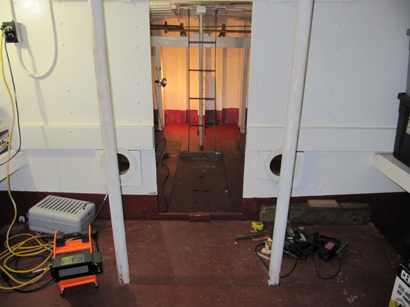
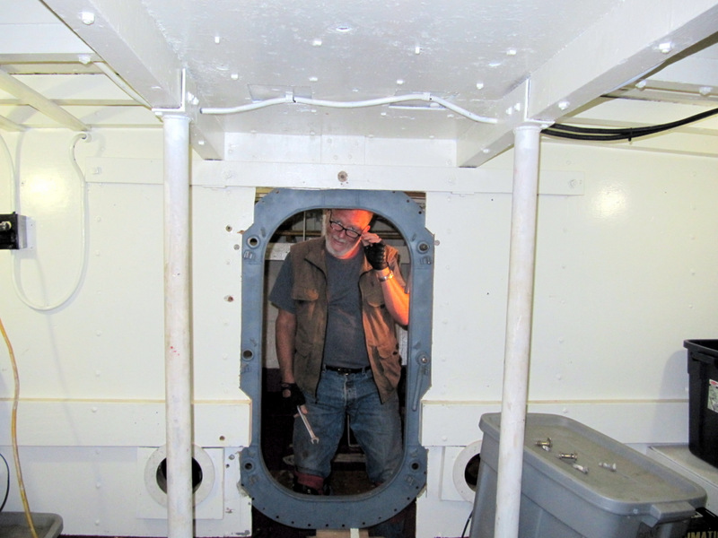
Looking aft from the hatch in aft engine
room bulkhead. (Not in original boats.) The opening seen in the bulkhead
will have a WTD installed soon.
Lazerett deck boards. Since this photo a
2nd and 3rd coat has been completed.
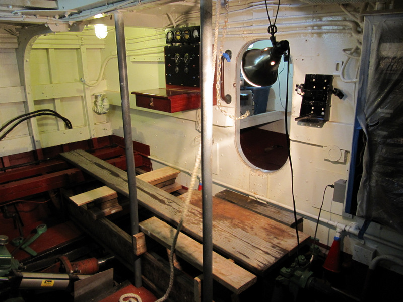
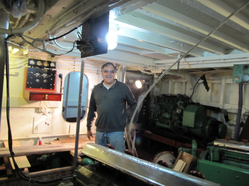
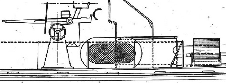
Restored engineering console mounted on
the aft engine room bulkhead.
Engine room, looking from forward to port
aft. Breaker panel has plastic over it for paint spray protection.
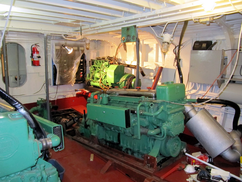
Engine room looking to Stbd aft corner.
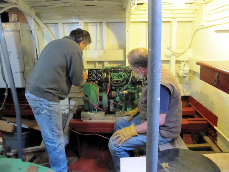
The old generator was removed since it was never going to run. A
replacement is almost ready for installation on these frame rails.
added 03-09-2012
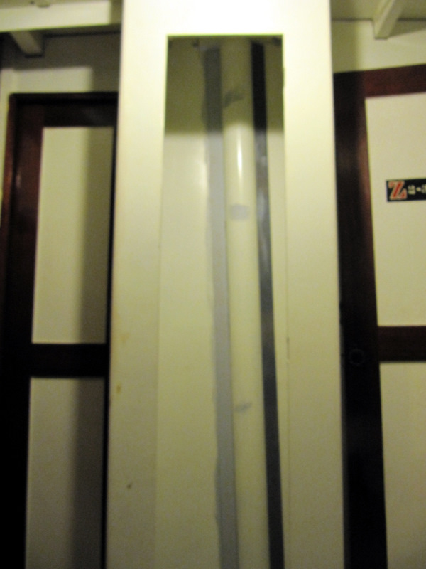
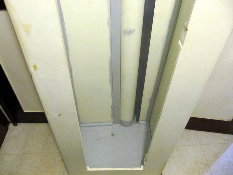
Closet in Chiefs Quarters. Setting on bunk
looking across.
Bottom of closet.
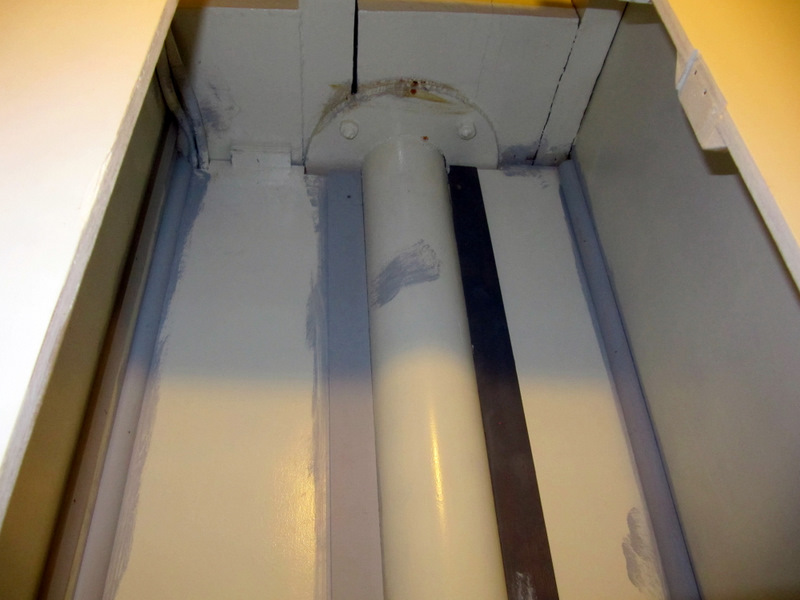
Top. Note pipe is at the base of the mast.
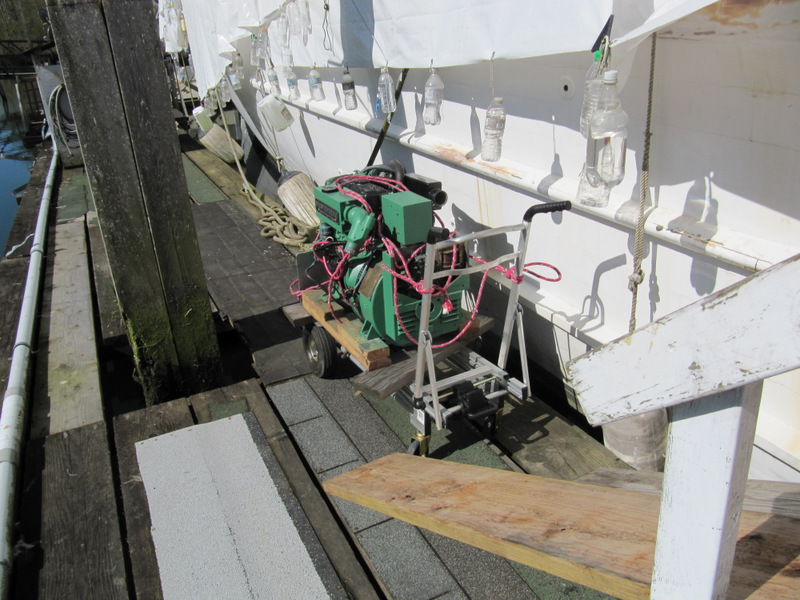
Added 04-17-2012
- The Starboard Generator Install.
Royal Journey planning some planks for a
future project.
The generator is down the ramp and the
foot of the boarding stairs.
Ready to use a come-a-long to pull it up
the planks, but the volunteers have not arrived.
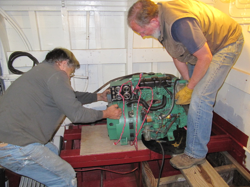
Engine room platform is in place ready to
receive the generator.
A plank platform is formed over the raw
water strainers to prevent any damage.
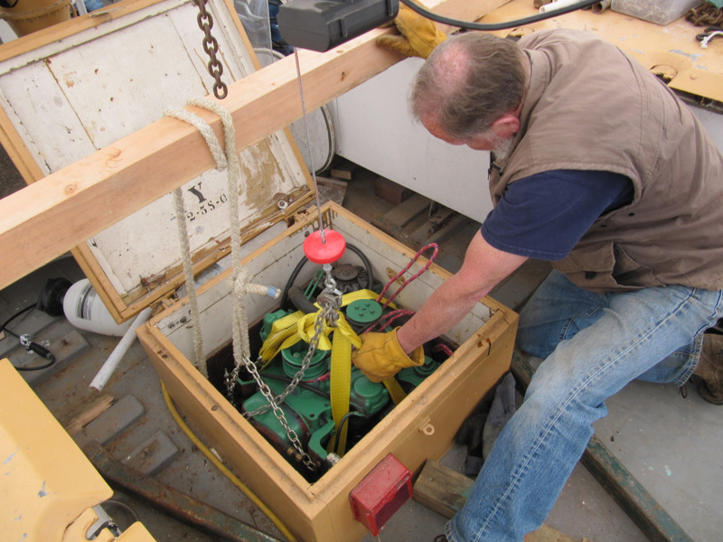
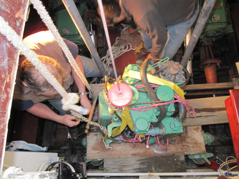
Mark McCaffery with generator ready to go
down the hole.
John Cross ready in the engine room to
guide and receive.
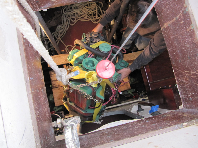
One last lift and remove the plywood and
2X4s.
Down the hole
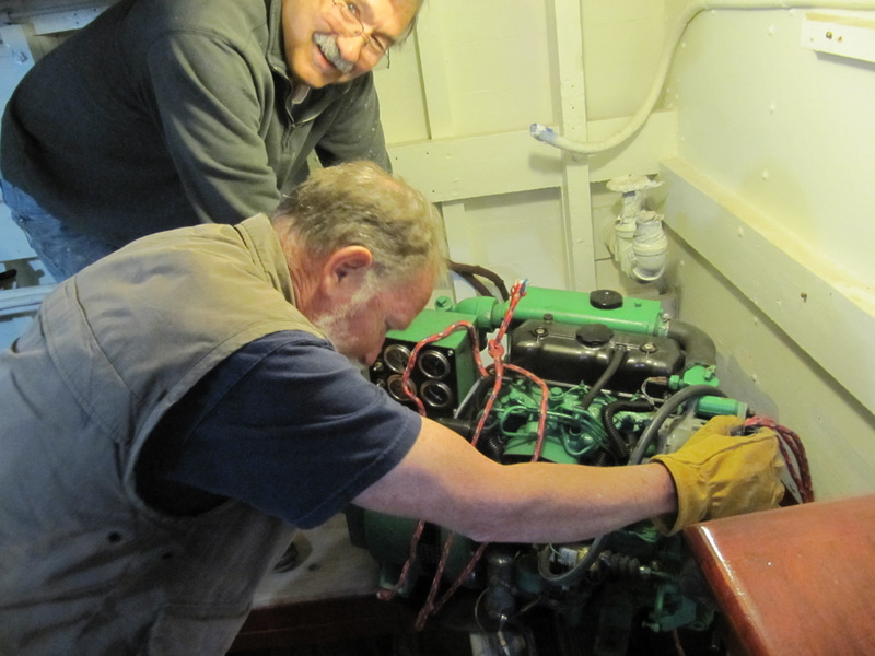
Cleared the obstacles.
Remove the strap and safety lines.
Getting ready to flop it over.
Grunting it across the plank to the bed.
One last push.
Its a wrap.
Added 06-26-2012
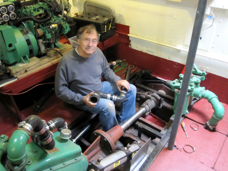
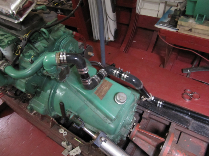
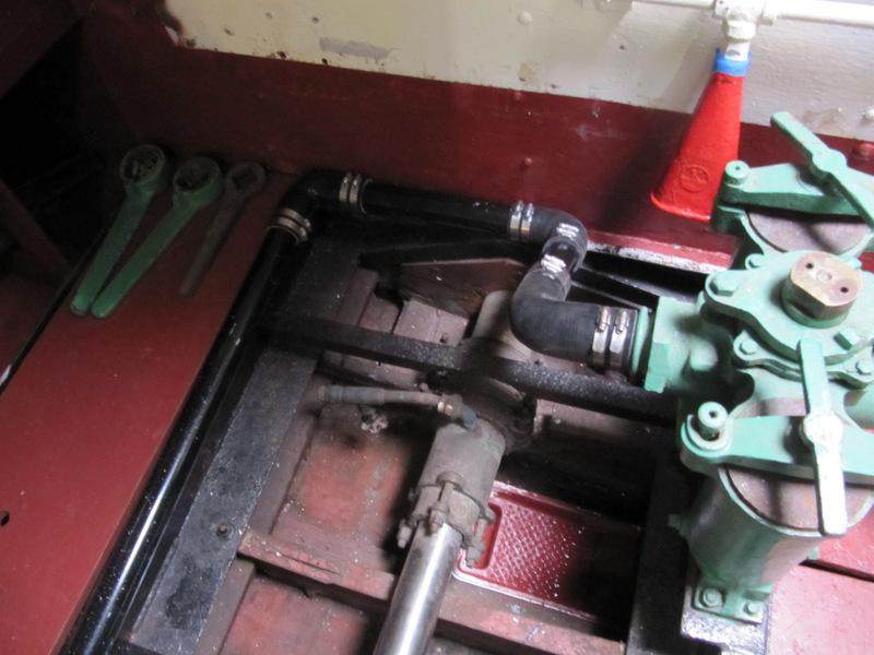
For the last 8 years the
raw water feed from the sea strainer was an ugly big hose supported by a
line from the overhead. That mess was replaced with 2" pipe and a
sequence of 90 degree connectors routed from the strainer to the pump
input. Several restraint clips need to be added. Here John Cross is
reassembling the segments.
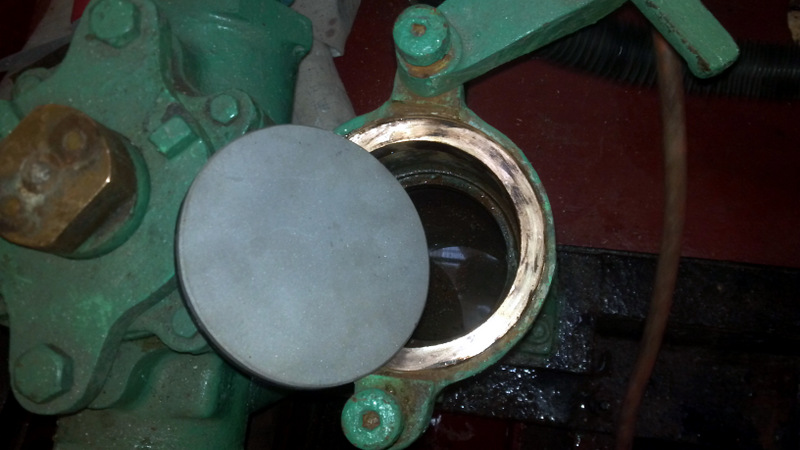
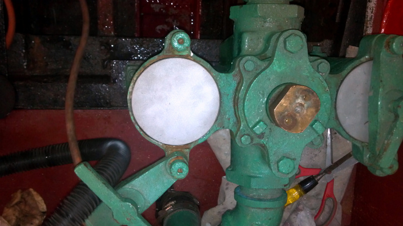
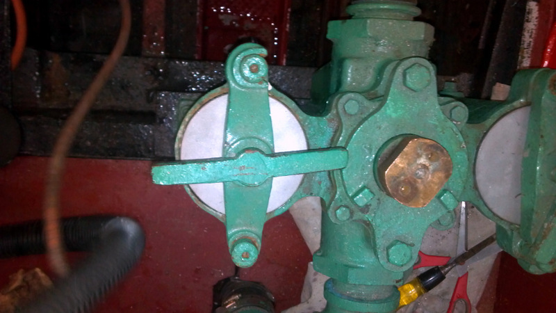
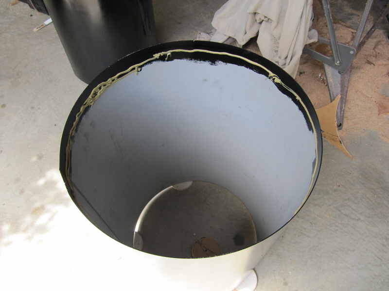
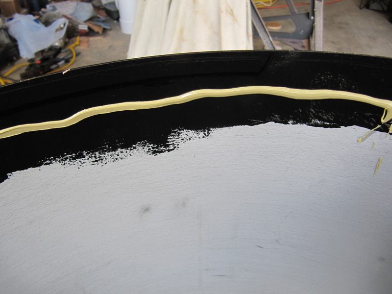
The port and stbd sea
strainer caps were severly rusted and replaced with new stainless steel
round plates.
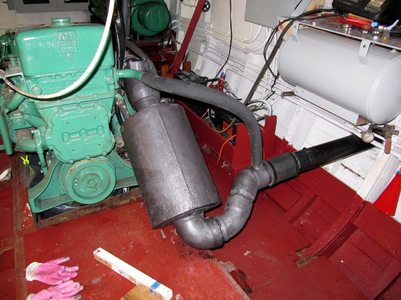
In early June after the
raw water system was reconditioned and reconnected we started up both
engines. After getting smoked out of the engine room we discovered that
the bottom edge of the port muffler was rusted through. That was removed
and a patch welded over the tired area and the muffler was reinstalled.
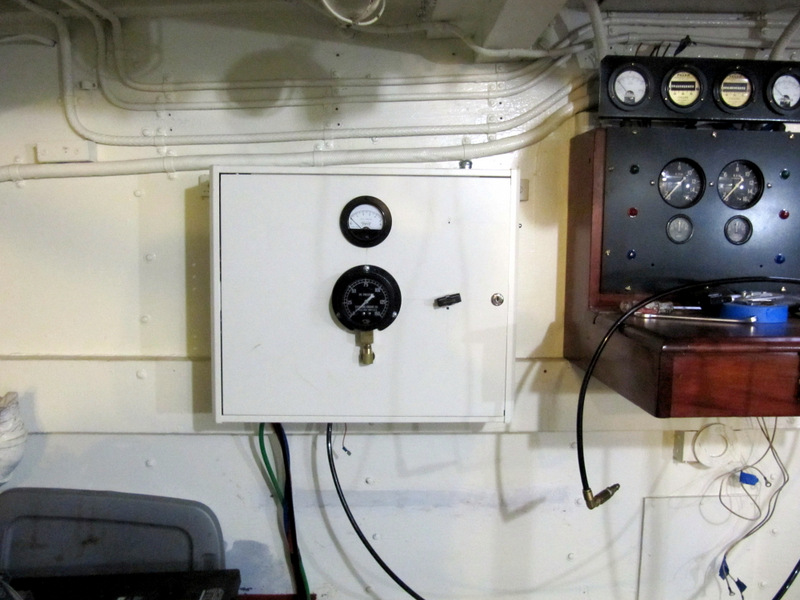
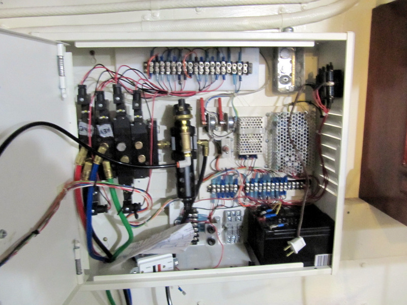
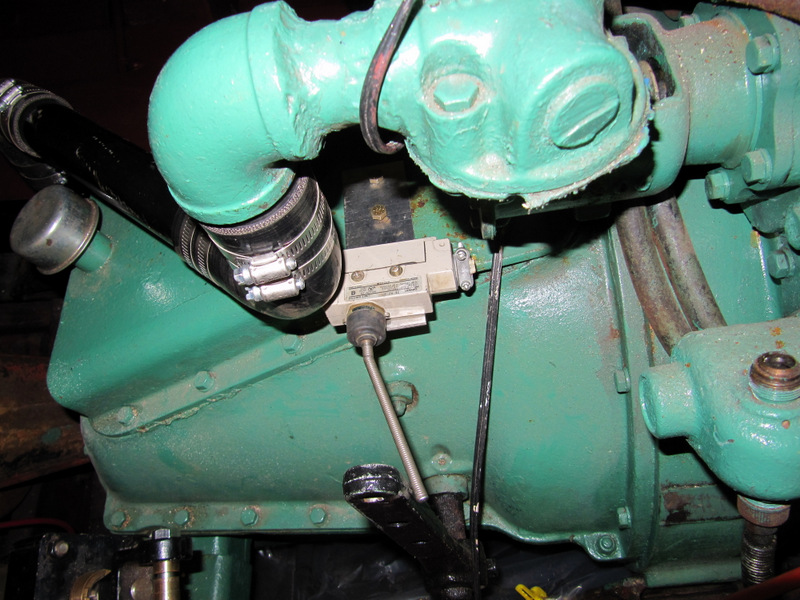
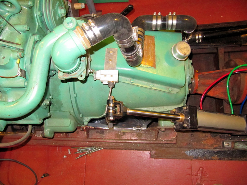
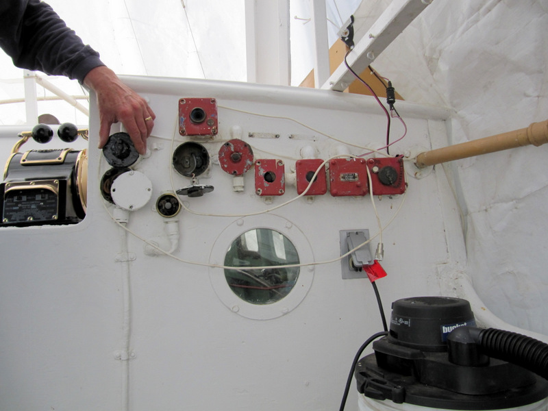
I finally got the air
shift control system smashed into an enclosure and wired up. The front
panel shows the air pressure at the manifold and the 24vdc for the
actuator valves. The selector switch provides three 24vdc voltage
sources for the system. The primary is 110vac from the generator
operating when underway. This powers a 24vdc output power supply. The
second source is a 12v to 24v inverter module that will run off of an
adjacent 12v battery (8D size nearby). The third is two small "alarm
box" type batteries in the enclosure. Since the whole system only
requires about 150 milliamps when operating there is almost no strain on
any of these sources. There is to be added an alarm horn for loss of 24v
or low air pressure. The air compressor arrangement is not yet
finalized. A complete description of this system will be provided later.
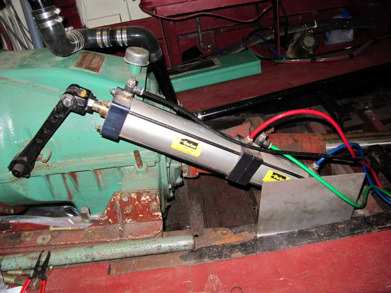
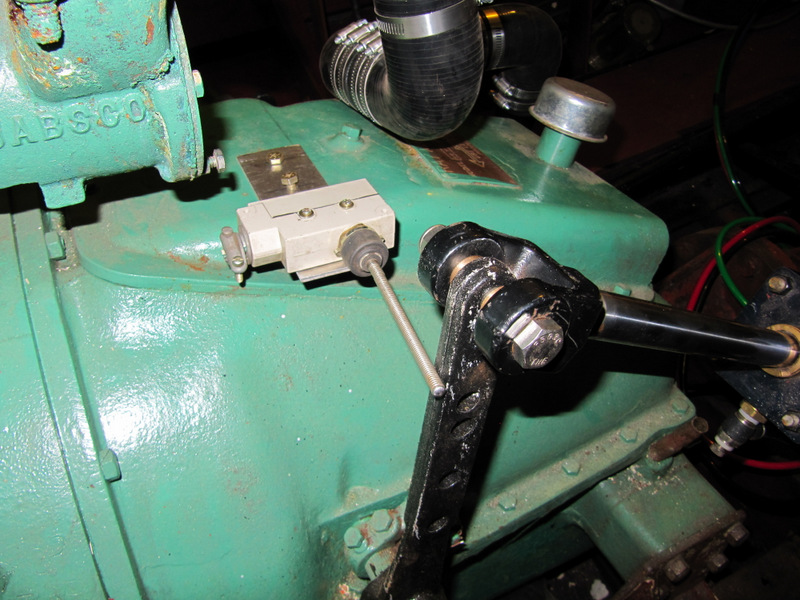
The switches in the below selection are the forward gear limit switches
adjusted to prevent the air valve from being activated when underway in
forward gear and prevent the cylinder from pushing the clutches against
the throwout bearing.
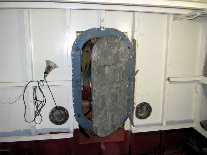
When we got the boat the
bulkhead between the lazarette and the spares compartment had a a big
cut out. Mark McCaffery and I have partially completed a watertight door
installation in that hole.
Other projects getting
completed include:
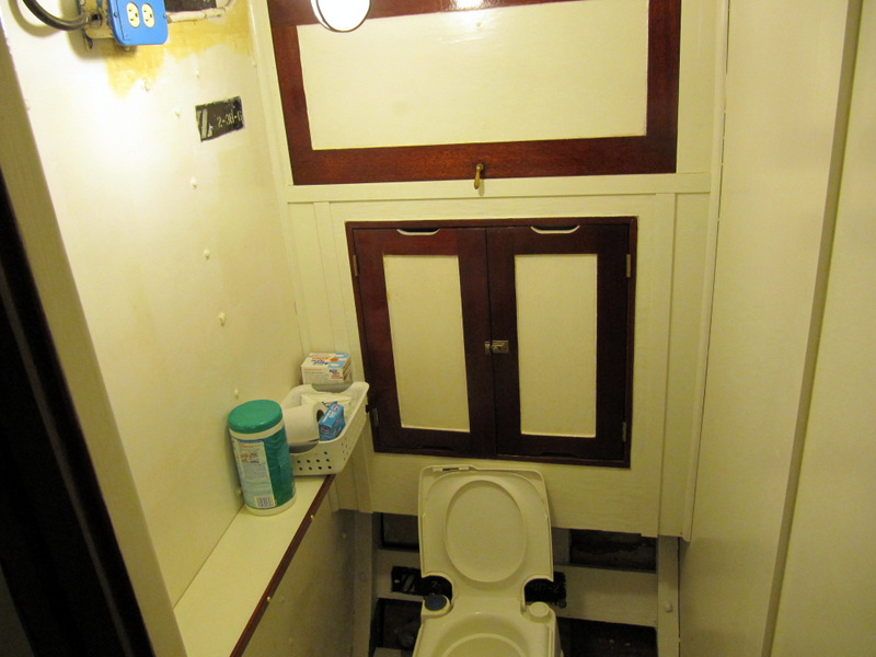
Chiefs head diddy bag
shelf added.
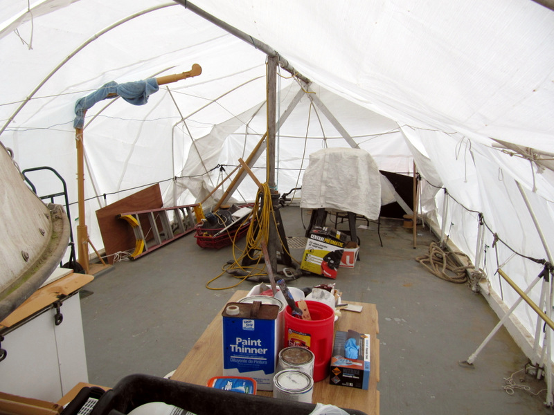
Massive cleanup and board pile removal on
the fantail.
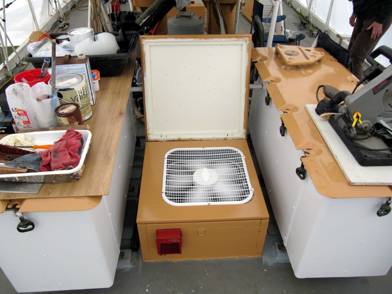
Engine room fan kludge for low power
cooling.
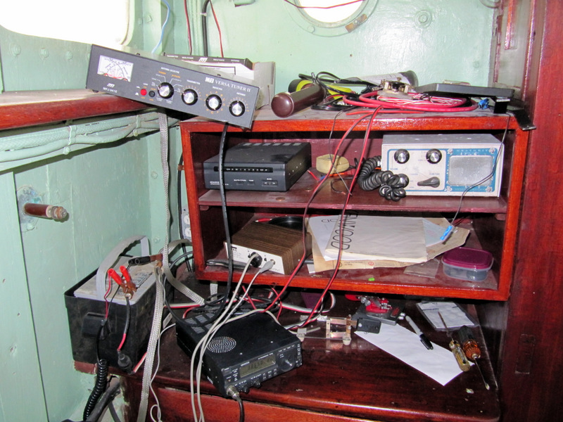
A thrown together ham shack for yakking
with ham radio friends.
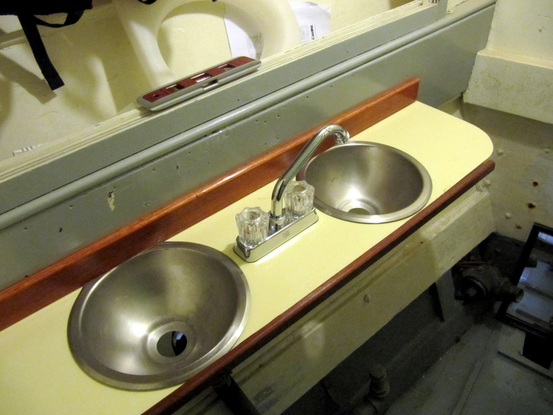
My interpretation of the forward head two
sink arrangement.
07-2012
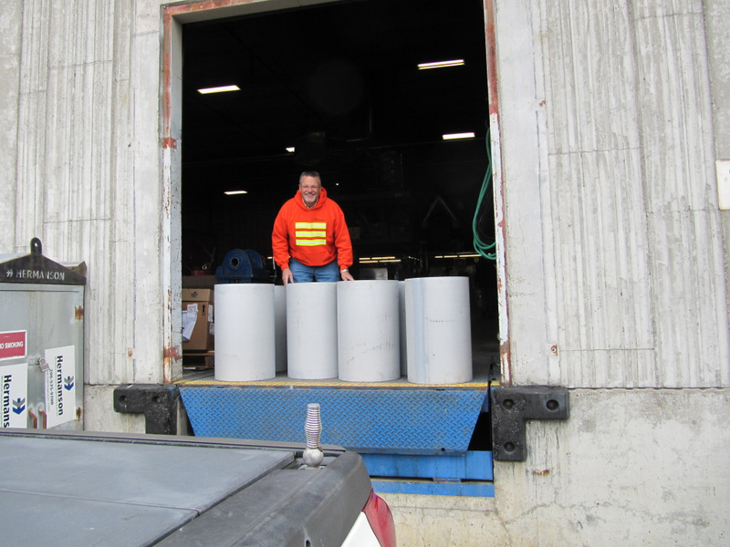
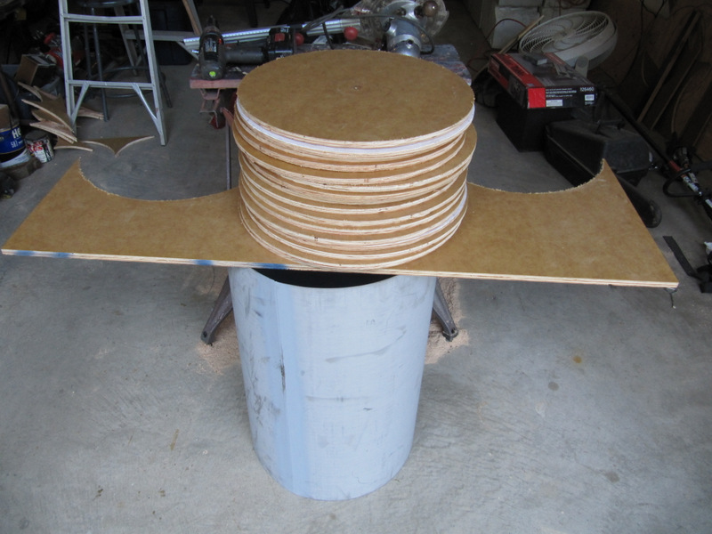
I'm picking up eight
cylinders the dimensions of a Mark VI depth charge. They were donated to
us by Rick Hermanson and the great people at
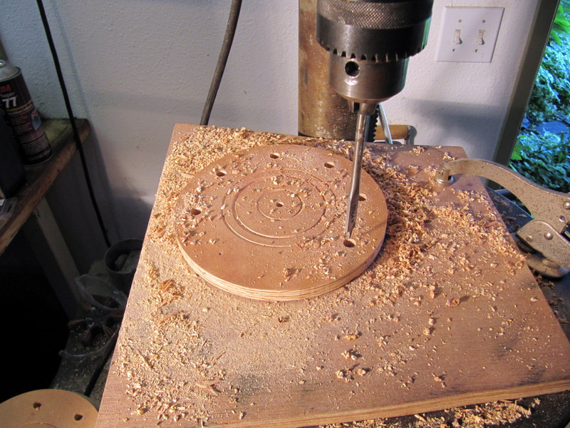
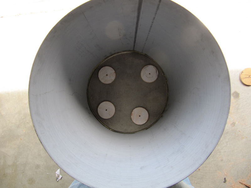
Routing out the end pieces for the depth
charges. Now for the detail add on pieces.
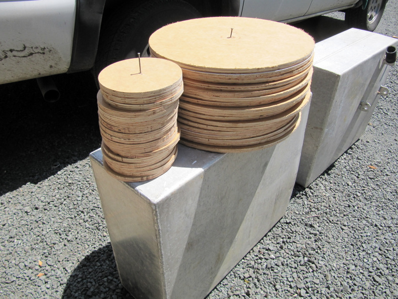
Ends and hub.
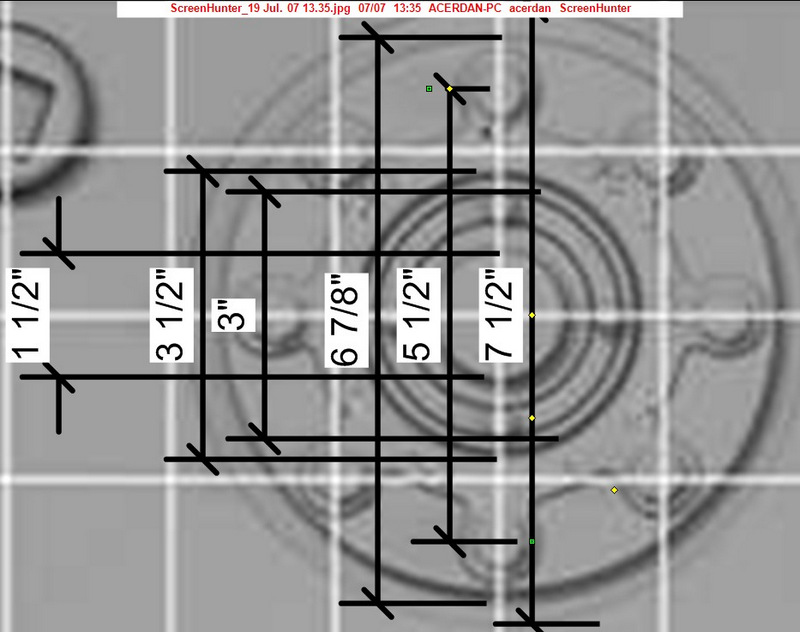
Hub detail dimensions.
Engraving fake details.
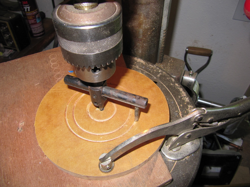
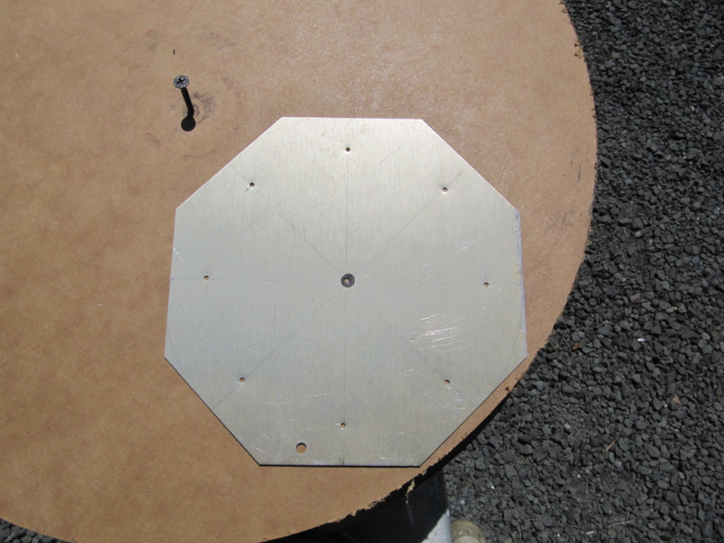
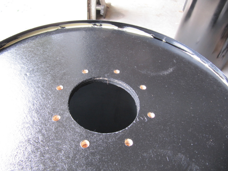
Hub drill template.
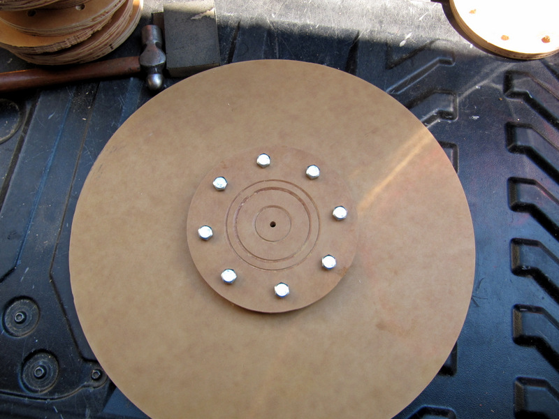
Drilling 3/8 inch holes in pattern.
Hub with bolts setting on end.
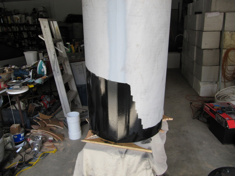
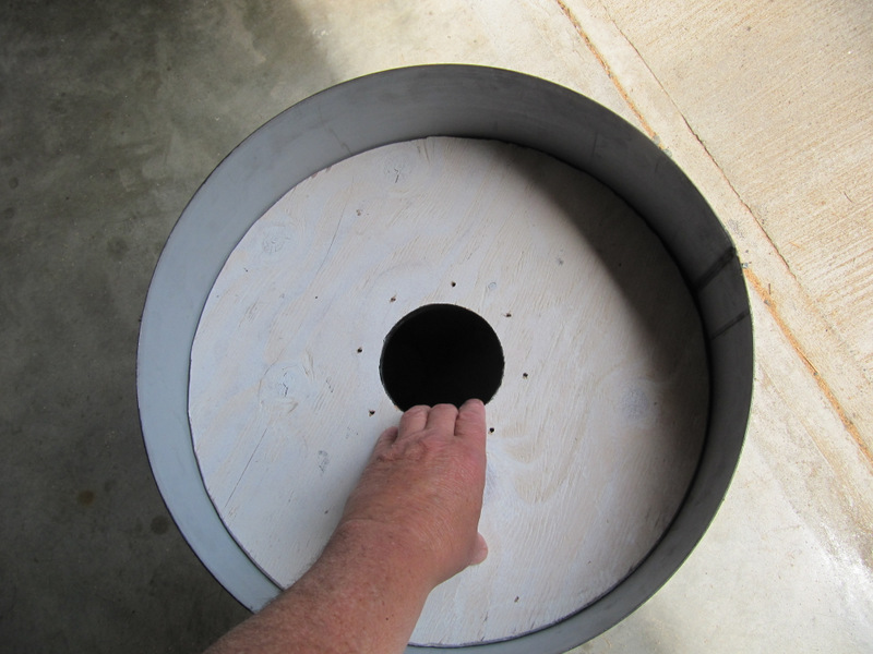
Painting cylinder
Painted
Apply Construction Cement
Cement
Spacer on deck to set in end panel
Spacers ready for panel.
Pushing panel into cement.
Applying cement behind panel
Cleaned up glue
Drying
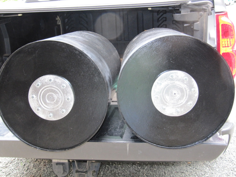
Painted hubs attached to end panel.
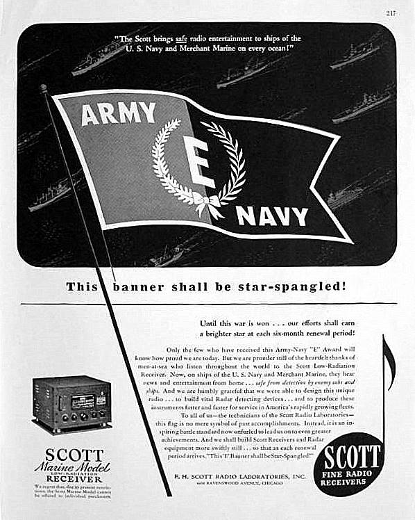
Panish Control advertisement found on Ebay.
With the basic airshift system operational
I got the Panish Control Box ready for installation on the flying
bridge.
Mike Mallet cleaning up the bridge and
area for control box placement.
Panish control setting in place.
This photo to document the location of the
switch and jack plates. They are getting removed and sand blasted, then
painted red as before.
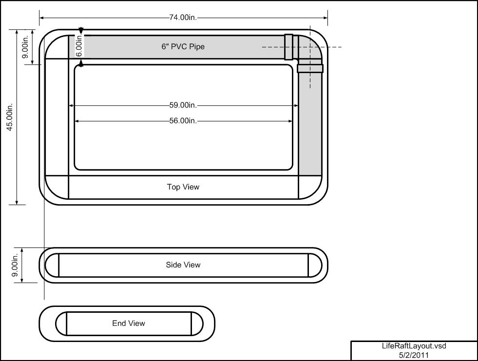
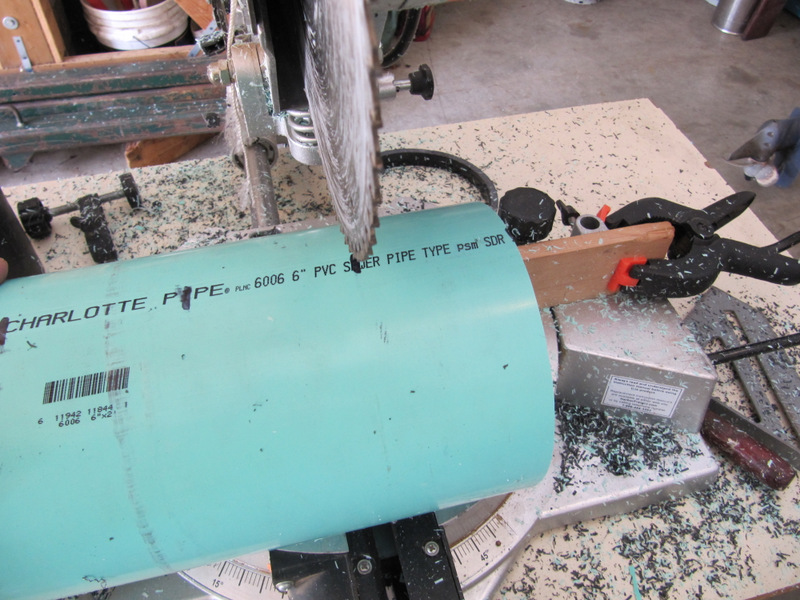
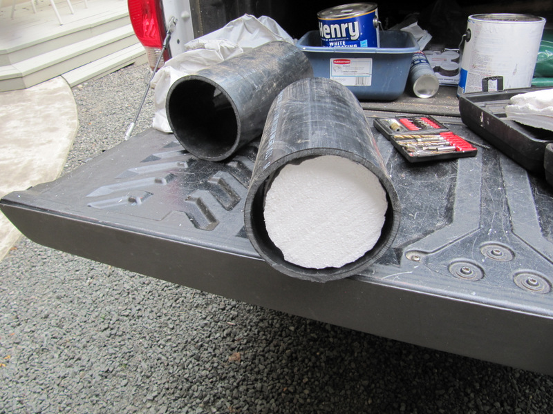
07-30-2012 Liferaft Project
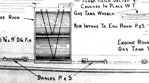
Many of the photos and drawings show balsa
life rafts aboard the 83'ers. This is an attempt to make some life raft
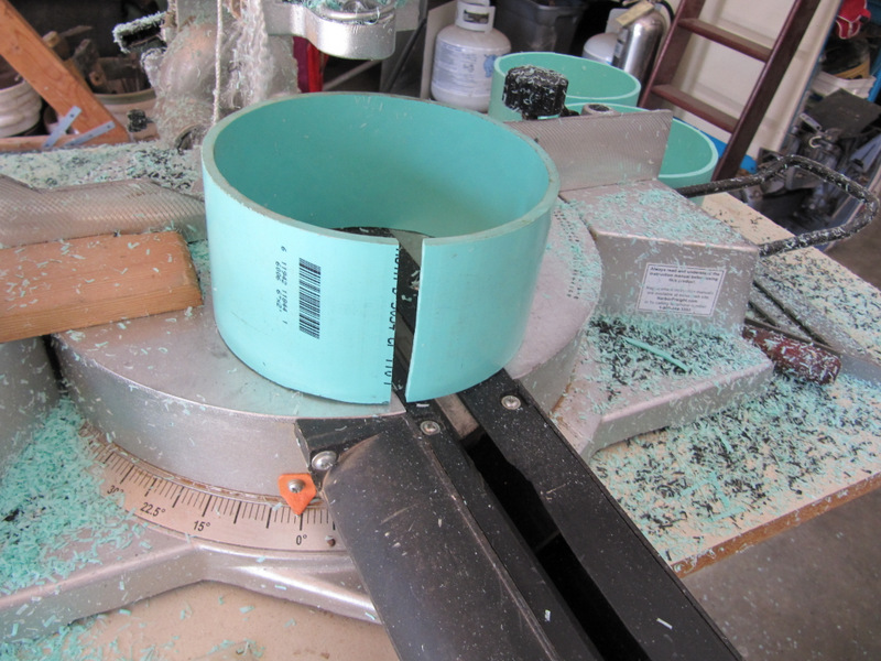
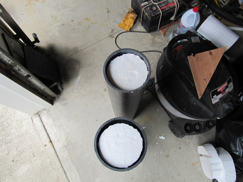
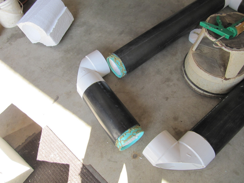
lookalikes. They are based on a core frame of 6" PVC pipe and "T"s.
Since this was a no budget project I scrounged all that I could. The PVC
pipe was donated by my friend Kim Bottles. The "T"s were purchased on
Craigslist in Bremerton for $4 ea. That was way better than $30 at
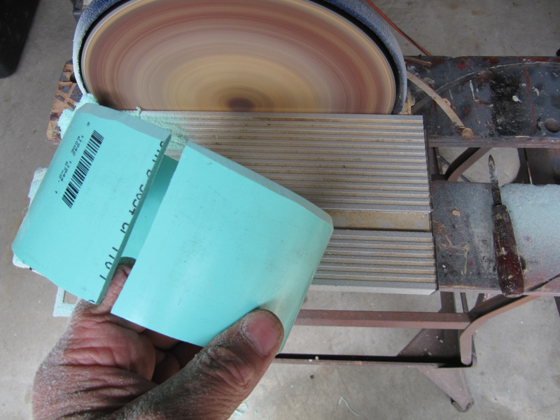
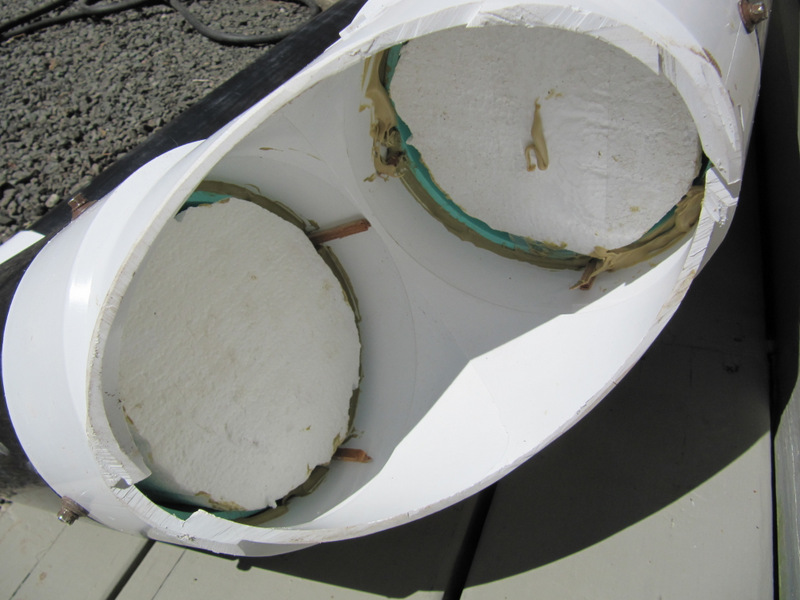
Lowes. After I got started I discovered that the PVC pipe, although
labeled 6" was for some reason unknown to me 6" ID, while the "T"s were
ready for 6" OD. This required a conversion spacer that was made out of
some 6" OD pipe. It made the original design way more complicated than
just joining 4 pipes to 4 90 degree corners.
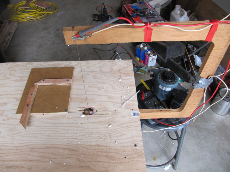
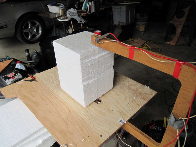
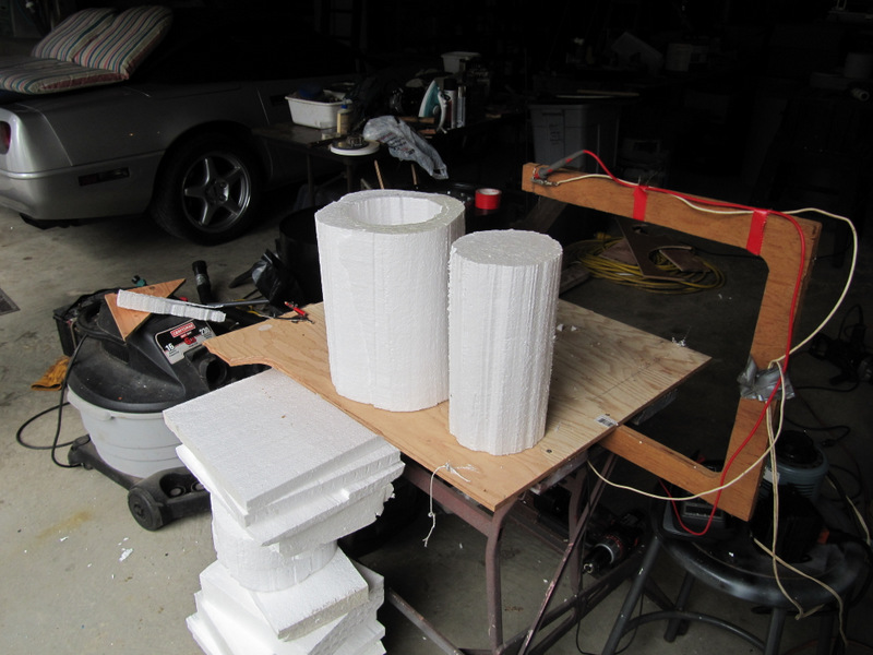
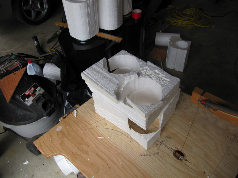
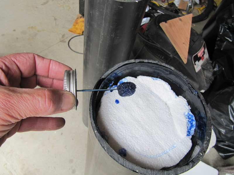
The shape of the raft
would be created with a 9" X 9"X 18" foam block. I scrounged about 30
12" x12"x 18" foam blocks from the Everett Lowes that were discarded.
The were used to space small trailers apart during shipment. I set up a
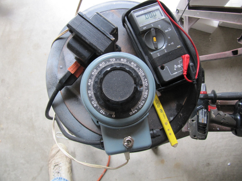
hot wire cutter frame that I scrounged from my neighbor, Royal Journey
and attached it to a piece of plywood on the work table. An AV voltage
variac was added to reduce the AC voltage down to about 9volts. That was
the perfect temp to easily slice the foam. So the blocks were sliced
down to the 9X9 dimension. Then with different rotating gadgets I made
the corners were rounded and the 9" core was removed. See the videos.